How to: Create and Edit Virtuals
This page is intended to give guidance on how to use virtuals.
TLDR;
Span Virtual
One effect on the virtual spread across multiple segments on multiple devices, note in this example there are significant difference in pixel counts between devices. Effects are copied ratio’d to the segments pixel counts.
Copy Virtual
One effect on the vitual copied to multiple segments on multiple devices irrespective of pixel count
So you want to know more?
Virtuals are a way to create a “virtual” device that can be assigned its own active effects. The virtual is then mapped into other devices.
With virtuals it is possible to
Have multiple physical devices running exectly the same effect, fully synchonised, irrespective of led count
Spread a single effect across multiple physical devices to slice that effect up into portions that are displayed on different devices
Use multiple strips or matrix blocks to make one large matrix, as long as they are vertically stacked
Devices vs Virtuals
Under the covers, in the dark depths of the LedFx code, there is a single virtual created for each device, automagically. it is these virtuals that the user interacts with via the UI, when assigning effects.
So mapping new virtuals to devices, is really mapping new virtuals to other virtuals, its virtuals all the way down.
Segments
When building virtuals, they are made up of segments of devices, you can select any range of pixels in any order. They don’t have to be complete devices, and the can be easily reversed.
Creating a virtual
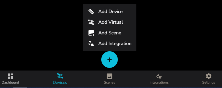
To add a new virtual, click on the large + icon at the bottom of the user interface and select Add Virtual
This will open the Add Virtual Device dialog
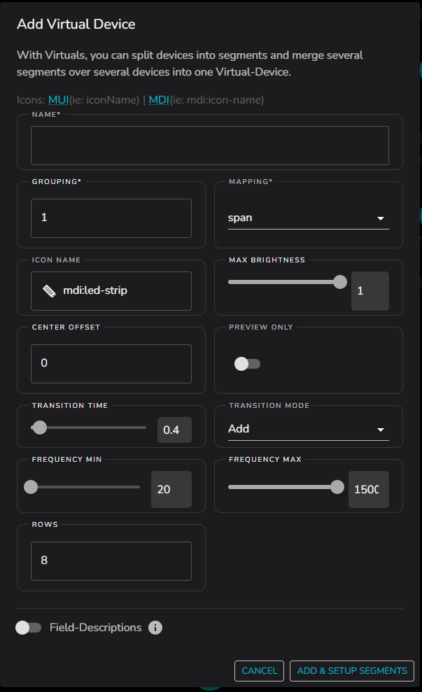
Thats a lot of options!!! Don’t worry, we can ignore most of them, but lets go over them all anyway first.
Name - Give the virtual a name, this is what you will see in the UI, make it meaningful, once you have a hand full of physical devices, and your own virtuals on top, you want to be able to find what you are looking for.
Grouping - This is a way to group pixels in a virtual or device into 1 pixel from the effect perspective, imagine you had a device with 10 LEDs but you want them to be treated as 1 pixel, you would set the grouping to 10. Generally leave this to default 1
Mapping - Important! This is where you select how the effect will be mapped into the segments that make up the virtual
span - A single instance of the active effect will be spread across all the segments that make up the virtual
copy - A copy of the active effect will be displayed on each segment that makes up the virtual
icon name - This is the icon that will be displayed in the UI, select something that makes sense to you. It is a string entry field, from MDI ( Material Design Icons ) or MUI ( Material UI Icons )
If using MDI the string should be preceeded by mdi:
“mdi: <icon-name-in-kebab-case>”
If using MUI the string should be just the icon name with out a prefix
“<iconNameInCamelCase>”
Max Brightness - This is the maximum brightness that the virtual will display at, from 0 to 1. Generally leave at 1
Center Offset - Pixel count by which to offset the center of the virtual when applying effects. Generally leave at 0
Preview Only - Preview the effect without updating the real devices. Generally leave off.
Transition Time - Length of transition when switching between effects.
Transition Mode - How to blend between old and new effects during transition. Modes are Add, Dissolve, Push, Slide, Iris, Through White, Through Black, None. Default is Add.
Frequency Min - Use to limit the low end of the frequency range for audio effects on this virtual.
Frequency Max - Use to limit the high end of the frequency range for audio effects on this virtual.
Rows - Number of rows in the virtual. For a 1d strip this is 1. For a 2d Matrix, set as desired. For example a 512 pixel 16 columns by 8 rows, would need this value set to 8.
Once all of these have been configured, the next step is to add and setup the segments that make up the virtual. So press the button handily marked as Add and Setup Segments
Adding a First Segment
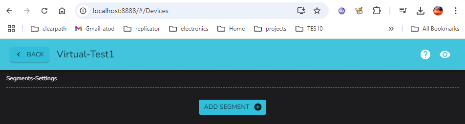
We are ready to add our first segment, press the Add Segment button
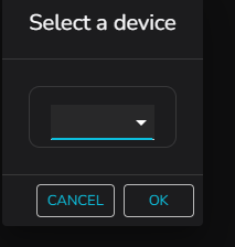
Hit the dropdown and a list of all devices will appear, select the device from which you want to assign your first segment
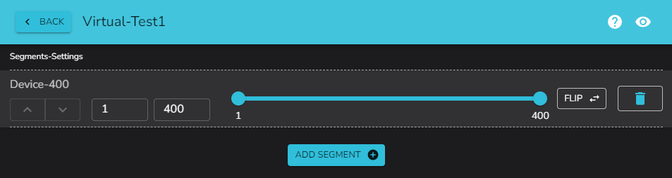
Our first added device happens to have 400 pixels, and we can see all are selected by default.
The currently selected segment under edit is animated live with a white wash pattern, with a dark bar showing the direction of effect mapping. This is displayed on the physical device, so you can directly see where you are building your virtual layout in the real world.
Adjusting the Segment
If we now set the start and end values by dragging the blue blobs, we can change the range for this segment
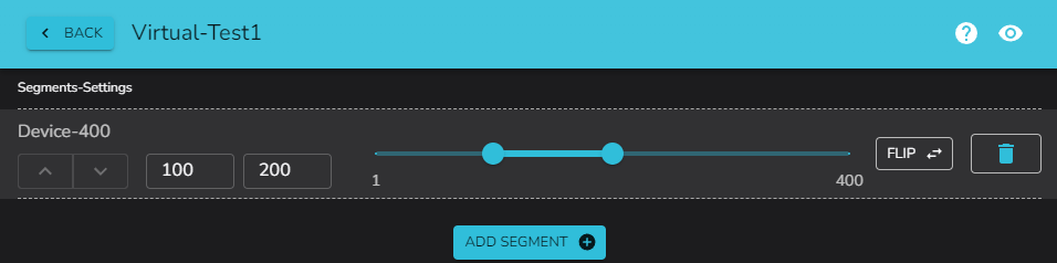
The live physical device will also update the white wash pattern to indicate the change as it is adjusted.
Adding a Second Segment
Now lets get tricky and add a second segment, on the same device. Using the sliders and watching the live wash, we will match them to fill the device. Note the active segment under edit is rendered in white, other segments in the virtual are cycled between red, green and blue, again with the wash implying the direction of render.
You SHOULD NOT save if your segments overlap, the UI will warn you if you try, however, if you leave the browser while in an overlapping configuration, you can generate a bad virtual config, which you will have to re-edit. Overlapping segments lead to undefined behaviour!
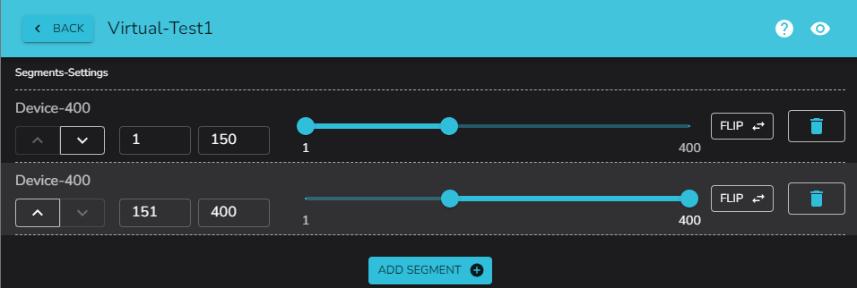
Note how the last edited segment is now white, and the other segment is one of red, green, blue, cycling to show direction
Let’s hit the flip button on one of those segments to show the changing of the render direction
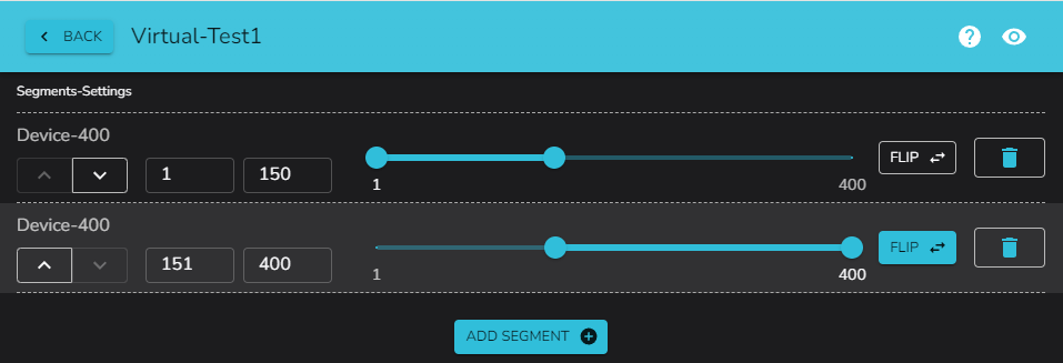
You can see the Flip button is now active and the impact on the live wash pattern
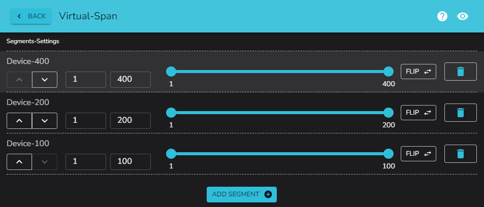
Adding a Few More Segments
Let’s add a few more segments on the other devices
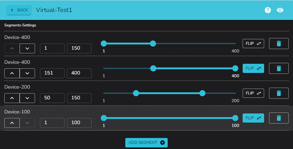
Note again in the live wash pattern, the last edited segment is white.
Now we are done, hit the back button. It is here that the UI would warn you if you had overlapping segments, so if you see a warning, go back and adjust the segments.
Using the pixels effect on the new virtual, we can see the effect spread across all the segments we have just created
Now you can add any effect to the virtual, and it will be spread across all the segments you have created. Or in this case we changed the virtual from a span to a copy, so the effect is copied to each segment, while observing the flip switch for directionality.
.…Profit
Segments can be changed in order, by using the up and down arrows, and deleted by using the trash can icon.
Segments are a very powerful tool to create complex virtuals to control your physical devices from a single effect dialog.
Remember that segments can also be used to stack matrix together in one dimension.
To build a larger matrix from smaller matrix blocks, ensure you stack them rather than tile.
For a 64x64 end matrix made up of 4 devices, you should configure into 4 devices of 16x64, not 4 of 32x32.
As we can only stack in one dimension, putting the 4 devices of 16x64 together via virtuals will allow you to achieve a 64x64 matrix controlled by a single virtual in ledfx.
Reserved Device Naming: Gap Devices
IMPORTANT: Avoid naming your devices with the gap- prefix.
What are Gap Devices?
Gap devices are special placeholder devices automatically created by the matrix editor in the frontend when building discontiguous LED layouts. These placeholders represent empty spaces in matrix configurations where no physical LEDs exist.
Identification
Gap devices are identified by both of the following criteria:
Device name starts with
gap-(e.g.,gap-0,gap-1)Device type is
dummy
Why This Matters
LedFx internally filters gap devices from runtime operations. If you
name your own devices with the gap- prefix and set them as dummy type,
they will be treated as gap placeholders and excluded from:
Pixel count calculations
Device flushing operations
Segment activation
Effect rendering
Best Practice
Do not name your devices starting with gap-. This naming convention
is reserved for internal use by the matrix editor. Choose descriptive
names like:
strip-1,matrix-main,bedroom-leds✓gap-device,gap-strip✗
If you have existing devices with gap- names, rename them to avoid
conflicts with the matrix editor’s placeholder system.